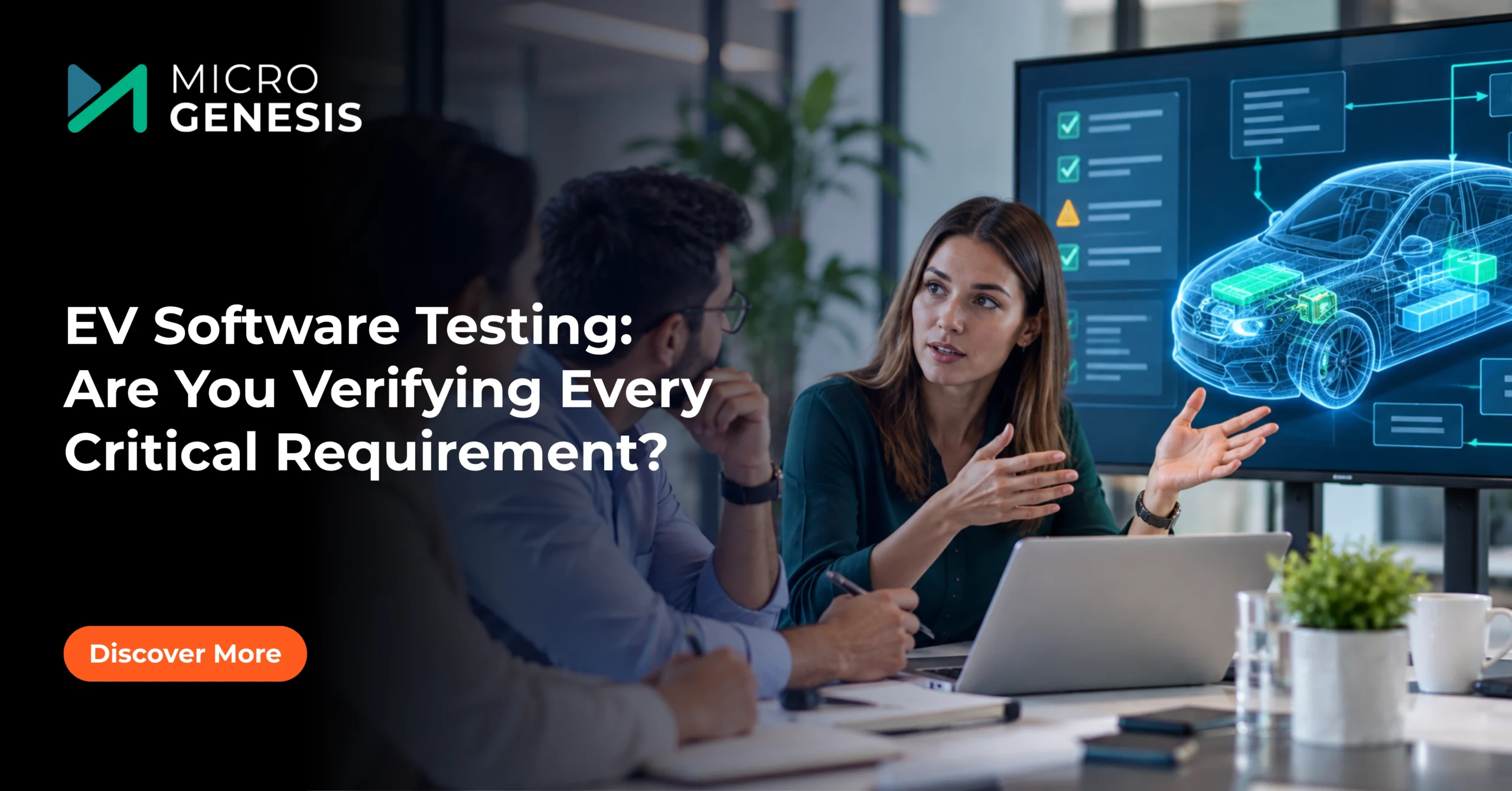
Electric vehicles depend on software for far more than displaying battery percentage or calculating driving range. Software controls battery charging, motor torque, regenerative braking, thermal management, energy distribution, and communication between electronic control units (ECUs). A software defect in any of these areas can affect vehicle performance, reliability, or safety.
Testing EV software introduces a particular challenge: engineers must verify how software behaves under normal driving conditions, unusual operating scenarios, and potentially hazardous faults without relying exclusively on physical vehicles.
A battery management system, for example, must estimate the battery’s state of charge, monitor cell voltages and temperatures, and respond appropriately when operating limits are exceeded. The motor control software must deliver the requested torque while respecting electrical, thermal, and system constraints.
Testing these behaviours requires a combination of simulation, hardware-in-the-loop (HIL) testing, controlled physical testing, and structured requirements traceability.
Let’s explore how automotive engineering teams can develop a practical EV software testing strategy that improves test coverage, supports safety objectives, and keeps verification evidence connected throughout development.
Why EV Software Requires a Different Testing Strategy
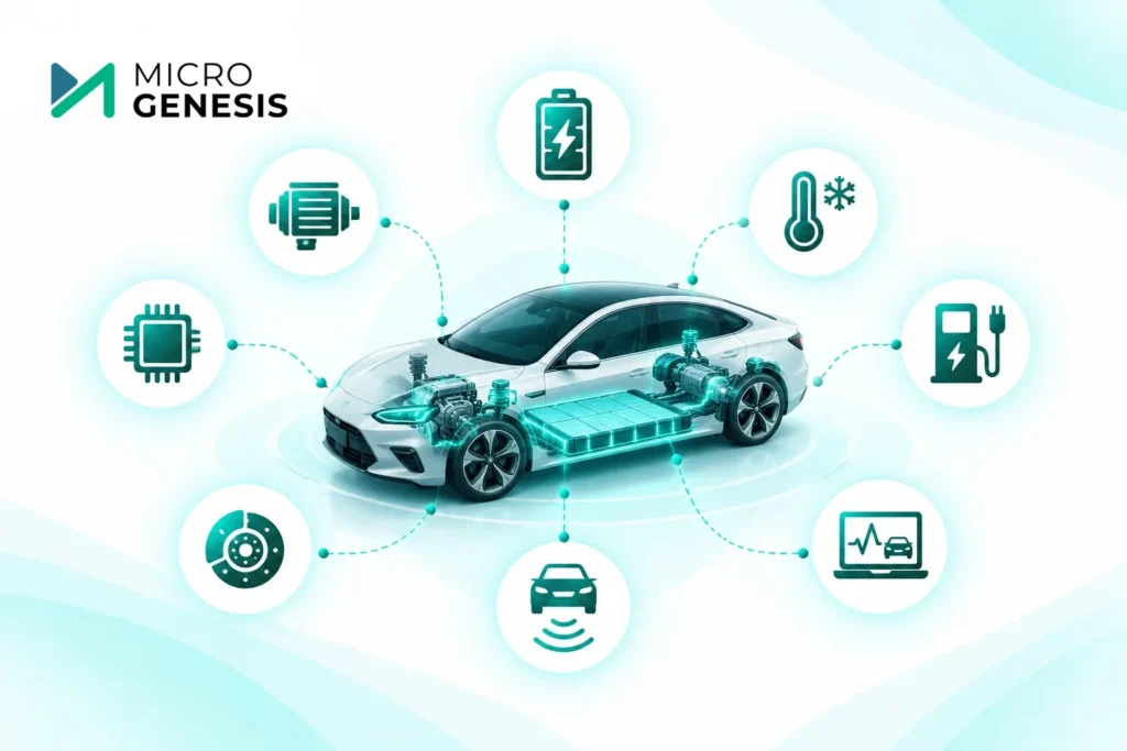
Traditional automotive software testing practices remain relevant to electric vehicles, but EV architectures introduce additional interactions between software, power electronics, batteries, charging systems, and thermal controls.
A fault in one subsystem can affect several others. For example, a battery temperature sensor reporting an incorrect value may influence cooling requests, charging limits, power availability, and diagnostic responses.
Testing each component independently is not enough. Teams must also verify how components behave together.
An effective EV software testing strategy should cover:
- Battery management system (BMS) functions, including voltage, current, temperature, and state estimation.
- Motor control functions, including torque requests, speed limits, and fault responses.
- Thermal management across batteries, motors, inverters, and cooling systems.
- Regenerative braking and coordination with conventional braking systems.
- Charging control, communication, and charging fault handling.
- Diagnostics, degraded operation, and recovery after faults.
- Interactions between software versions, hardware configurations, and vehicle variants.
The right approach combines different test levels rather than relying on a single technique. For an overview of the broader process, see automotive software testing best practices.
HIL Testing for Battery and Motor Control Systems
Hardware-in-the-loop testing is particularly valuable in EV development because it allows engineers to test a real controller against a simulated vehicle or subsystem environment.
Instead of connecting the controller to an entire physical vehicle, a HIL setup uses real-time simulation to reproduce the behaviour of components such as the battery pack, electric motor, inverter, vehicle dynamics, and sensors. The controller receives simulated inputs and produces outputs that the test system measures and evaluates.
This makes it possible to test repeatable scenarios, including faults and operating conditions that would be difficult, expensive, or unsafe to reproduce in a real vehicle.
HIL testing for battery management systems
A BMS must monitor battery conditions and help keep the pack within its permitted operating limits. Engineers need to verify both normal operation and responses to abnormal inputs.
Useful HIL test scenarios include:
- Cell overvoltage: Simulate a cell voltage exceeding its permitted limit and verify that the BMS responds according to its specified strategy.
- Temperature sensor faults: Introduce open-circuit, short-circuit, or implausible sensor readings and check diagnostic and protective responses.
- Current measurement errors: Simulate inaccurate current readings and assess how the software detects or handles the condition.
- Communication failures: Interrupt communication between the BMS and other controllers to verify timeout handling and defined fallback behaviour.
- State estimation: Evaluate state-of-charge and state-of-health algorithms across representative operating conditions, using suitable reference data.
Consider a vehicle approaching a fast charger when a battery temperature sensor starts reporting an implausible value. The test should verify whether the BMS detects the problem, reports the fault, and applies the specified charging restrictions or fallback response.
The objective is not merely to confirm that an error message appears. Engineers must verify the complete expected response, including diagnostics, control actions, and interactions with other vehicle systems.
HIL testing for motor control systems
Motor control software needs to respond accurately to driver torque requests while accounting for operating limits and faults.
HIL testing can evaluate scenarios such as:
- Torque response during acceleration and regenerative braking.
- Motor speed limits and torque restrictions.
- Inverter fault signals and communication loss.
- Sensor failures affecting rotor position or speed estimation.
- Transitions between drive, coast, and regenerative braking.
- Behaviour during rapid changes in requested torque.
For example, when an inverter fault is reported, engineers should verify that the motor controller follows the defined fault-handling strategy. The expected result may involve limiting torque, disabling a function, reporting a diagnostic code, or entering a specified degraded mode.
The exact response depends on the system design and safety requirements.
Where HIL fits in the testing lifecycle
HIL testing is most effective when it builds on earlier verification rather than replacing it. Software unit tests and model-level testing can identify many issues before the controller is connected to a HIL rig. HIL then allows engineers to evaluate real controller hardware, interfaces, timing, and fault responses under repeatable conditions.
Physical testing remains necessary to validate real-world behaviour, particularly where the accuracy of simulation models, electromagnetic effects, mechanical interactions, or environmental conditions matters.
For a structured approach to planning these activities, explore test lifecycle management for regulated software.
If your team is reviewing its verification process across embedded software, requirements, and test evidence, MicroGenesis ALM services can help you assess the lifecycle management and integration practices needed to support that process.
Thermal, Safety, and Abuse-Case Testing
EV software must respond appropriately when operating conditions move beyond the normal range. This makes thermal behaviour, fault handling, and abuse-case testing important parts of the overall verification strategy.
One important distinction: software testing can verify detection, control, diagnostics, and protective responses. It does not replace physical battery abuse testing, component qualification, or vehicle-level safety validation where those activities are required.
Thermal testing: Beyond normal operating temperatures
Battery performance and charging behaviour depend heavily on temperature. The battery management and thermal control systems must respond to temperature measurements, cooling-system availability, charging demand, and operating limits.
Test scenarios may include:
- High battery temperatures during sustained power demand.
- Low-temperature conditions that restrict charging or power delivery.
- Cooling pump or fan failures.
- Implausible temperature readings.
- Thermal sensor disagreement.
- Changes in thermal conditions during charging and driving.
For example, imagine an EV climbing a long incline on a hot day. Battery and motor temperatures rise, and the controller must manage available power according to the system’s control strategy. Testing should establish whether temperature thresholds trigger the intended cooling requests, torque limits, warnings, and diagnostic behaviour.
Engineers should also test transitions between states. A controller may respond correctly when a temperature limit is first exceeded but behave incorrectly when the temperature falls again. Recovery conditions, hysteresis, and repeated threshold crossings therefore deserve attention.
Safety testing: Verify the response, not just the fault detection
EV safety-related software may need to detect faults and move a system into a defined safe or degraded state.
Testing should consider:
- Sensor faults and inconsistent measurements.
- Communication interruptions between controllers.
- Invalid or out-of-range control commands.
- Failure of a required monitoring function.
- Unexpected controller resets.
- Fault detection, diagnostic reporting, and recovery behaviour.
Suppose a motor controller loses a critical input signal. It is not enough to verify that the controller logs a diagnostic code. Engineers must also confirm that the resulting control behaviour matches the system’s safety requirements and that recovery occurs only under the specified conditions.
For background on the engineering principles involved, read what is functional safety?. Where functional safety applies, test planning and evidence should align with the safety lifecycle and the project’s applicable ISO 26262 requirements. The required activities depend on the system, its safety classification, and the development context.
Abuse-case testing: Plan for abnormal and hazardous conditions
Abuse-case testing examines how a system responds to conditions outside its intended operating envelope. In EV development, these scenarios can include incorrect sensor inputs, unexpected charging states, communication failures, and combinations of faults.
Battery abuse testing can also involve physical conditions such as overcharge, external heating, or mechanical damage. These tests require appropriate laboratory controls, specialist equipment, and safety procedures. They should not be treated as ordinary software-only tests.
A practical strategy separates the activities:
- Use simulation and HIL to test software responses to representative fault conditions.
- Use controlled hardware and component tests to evaluate relevant electrical and thermal behaviours.
- Use system and vehicle testing to validate integrated responses in representative configurations.
- Connect results to the requirements and risk controls they are intended to verify.
For additional context on safety and process expectations, see ASPICE vs ISO 26262.
Test Traceability for EV-Specific Requirements
A test can pass and still leave an important question unanswered: Which requirement did it verify, and does the result apply to the vehicle configuration being released?
This matters in EV programs because a single requirement may affect several components, software versions, battery configurations, or vehicle variants. Testing records need to demonstrate more than a successful execution. They need to show what was tested, under which conditions, against which requirement version, and with what result.
Build a connected requirement-to-test chain
A typical traceability chain for an EV function may look like this:
EV System Requirement → Software Requirement → Design or Model → Implementation → Test Case → Test Result
Additional links may connect the requirement to hazards, safety analyses, diagnostic records, defects, change requests, and release baselines where applicable.
Consider a requirement stating that the battery management system must detect a specified overtemperature condition and initiate a defined response.
The test evidence should identify:
- The exact requirement and its approved version.
- The applicable battery and software configuration.
- The temperature input and fault conditions used.
- The expected detection and control response.
- The actual result and pass/fail status.
- Any deviations, defects, or follow-up actions.
- The test environment and relevant execution records.
If the requirement changes, the team should be able to identify the associated tests and assess whether they must be updated or rerun.
This is especially important when requirements are shared across several vehicle variants. A test result from one battery configuration should not automatically be considered valid for another without checking the applicability of the result.
For more guidance, read the importance of requirements traceability and engineering traceability.
Avoid disconnected test records
In many engineering organisations, requirements are managed in an ALM platform, automated test results are stored in a test execution environment, defects are tracked separately, and release evidence is maintained in documents.
This can create gaps when teams rely on spreadsheets or manual updates to connect the information.
A better approach is to establish consistent identifiers, define ownership for each artifact, and integrate requirements management with test management wherever practical. Automated checks can flag requirements without verification links, tests associated with obsolete versions, and unresolved changes that affect release readiness.
See integrating test management with requirements tools for approaches to connecting these workflows.
For teams managing complex EV requirements and verification activities, IBM Engineering Lifecycle Management services can be relevant when evaluating enterprise requirements, test management, and lifecycle integration needs.
Combining Manual, Automated, and HIL Testing
No single testing method is sufficient for an EV software program. The most effective strategy uses different techniques for different risks and stages of development.
Testing approach | Best suited for |
Unit and software tests | Verifying individual functions, algorithms, and boundary conditions |
Model-based simulation | Exploring system behaviour and scenarios early in development |
HIL testing | Testing real controllers against repeatable simulated environments and injected faults |
Automated regression testing | Repeating selected tests after code, configuration, or requirement changes |
Manual testing | Investigating unexpected behaviour, exploratory scenarios, and cases requiring engineering judgement |
Physical component and vehicle testing | Validating hardware interactions, environmental effects, and integrated real-world behaviour |
Automation is particularly useful for repeating battery and motor control tests after software changes. However, automated execution does not guarantee good coverage. Test scenarios, expected results, simulation models, and configuration data must be maintained carefully.
Manual investigation also remains important when a result is unexpected or the scenario requires interpretation.
A sensible starting point is to identify high-risk EV functions, define the required evidence for each, and determine which tests should run at the unit, model, HIL, component, and vehicle levels.
For a deeper comparison, see manual vs automated test management.
How MicroGenesis Can Help Improve EV Test Management
As EV software becomes more interconnected, test management increasingly depends on the quality of the engineering workflow behind it. Teams need to manage requirements, connect verification evidence, control changes, and understand the status of testing across software versions and vehicle configurations.
MicroGenesis supports organisations with ALM consulting, implementation, and lifecycle integration services that can help establish these capabilities.
Depending on the engineering environment, the work may include:
- Requirements-to-test traceability: Establishing links between EV-specific requirements, test cases, execution results, and changes.
- Test management process improvement: Defining consistent workflows for test planning, execution, defect handling, and evidence management.
- ALM tool implementation: Configuring lifecycle processes to match engineering and verification needs.
- Toolchain integration: Connecting requirements and test management systems to reduce manual handovers and fragmented records.
If your organisation is reviewing its EV software verification workflow, start with MicroGenesis ALM services to explore how lifecycle management practices can support connected engineering processes.
You can also learn about Codebeamer ALM for requirements, test management, and traceability needs, or review IBM Engineering Lifecycle Management for enterprise lifecycle management requirements.
The right approach depends on your current tools, verification process, system architecture, and evidence requirements. A focused assessment can help identify the most important gaps before committing to broader toolchain changes.
Final Thoughts
EV software testing requires more than confirming that battery and motor controllers work under normal conditions. Engineering teams must evaluate thermal behaviour, fault responses, abnormal operating scenarios, and interactions between interconnected vehicle systems.
HIL testing provides a controlled way to verify real controllers against simulated conditions. Thermal and abuse-case testing help teams assess behaviour beyond routine operation. Requirements traceability connects these activities to the engineering decisions and evidence needed throughout development.
The practical goal is to make every important EV requirement verifiable and every test result meaningful. When teams can identify what was tested, under which conditions, and against which requirement version, they are better equipped to manage changes, investigate failures, and prepare for release reviews.
A strong EV software test strategy combines the right test methods with reliable traceability, so that engineering teams can demonstrate not only that a test passed, but also what that result proves.